

Vacuum technology and filtration are two important technologies that are used in many different industries, including chemical, biotechnology, food and pharmaceuticals.
In vacuum technology, a vacuum is used to accelerate or carry out technical processes. These include vacuum filtration.
Filtration is a physical separation process in which particles (macromolecules, micro-organisms, viruses or droplets) are separated from a fluid (gases or liquids) by means of a filter medium (e.g. paper, glass fibre or membrane filters).
► Carl ROTH offers you an extensive product portfolio for your specific application needs.
Vacuum technology
The heart of vacuum technology is the vacuum pump. It is a versatile tool, used in many sectors and industries, but also in research and analysis laboratories.
It is used, among other things, for vacuum filtration, evacuation of desiccators, degassing processes, drying processes in vacuum drying cabinets or vacuum gel dryers, solid phase extraction, vacuum distillation, solvent evaporation in rotary evaporators or for the extraction of liquids.
Depending on the application, specific requirements are placed on the vacuum pump concerning the delivery rate, ultimate vacuum, controllability, chemical resistance and condensate compatibility, among other things.
Definition of vacuum
Using a vacuum pump, gas or air particles are sucked in and released again. When used in a closed system, the pressure drops below atmospheric pressure (1013 mbar at sea level) and a vacuum is created.
The deeper the vacuum, the fewer gas molecules are present. The vacuum is divided into different areas:
- Low vacuum (1000 to 1 mbar)
- Medium vacuum (1 to 1x10⁻³ mbar)
- High vacuum (1x10⁻³ to 1x10⁻⁷ mbar)
- Ultra-high vacuum (1x10⁻⁷ to 1x10-14 mbar)
Classification of vacuum pumps
A vacuum can be created with vacuum ejectors, positive displacement vacuum pumps or kinetic vacuum pumps:
- Water jet pumps belong to the vacuum ejectors and function according to the Venturi principle.
- A positive displacement vacuum pump draws the air into a chamber, where it is mechanically trapped, compressed and expelled again. These pumps include piston vacuum pumps, diaphragm vacuum pumps, rotary pumps and screw pumps.
- Kinetic vacuum pumps convey the gas to the outlet according to the principle of momentum transfer by accelerating it in the pumping direction via high-speed blades or steam supply.
- Our product portfolio includes simple water jet pumps, oil-free piston, diaphragm and screw pumps, oil-sealed rotary pumps, fully equipped vacuum systems and extraction systems.
As accessories, we offer vacuum gauges to indicate the vacuum, manual vacuum regulators and automatic vacuum controllers to scale and control the ultimate vacuum, and much more.
Water jet pumps
Structure/functionality
A water jet pump is a very simple jet pump that uses water as the motive medium in a venturi nozzle. It consists of two inlets (inlet pipe (1) and suction pipe (2), one outlet (outlet pipe (3)) and a mixing pipe (4).
By narrowing the cross-section of the inlet pipe to a nozzle (5), the introduced water jet (from the existing water connection) is accelerated. The pumped medium is carried away from the suction line and exits at the outlet, together with the water.
Advantages
- Water jet pumps are low-maintenance, as they have no moving parts or seals.
- They are easy to use and only require a water source.
- Purchasing costs are low
Our Carl ROTH online shop has two types of water jet pump. Depending on the available water pressure, either a standard water jet pump or a low-pressure water jet pump is required.

Disadvantages
- Operating costs are high due to heavy water consumption.
- Depending on which vapours are drawn in from the application, the waste water may be contaminated.
- Water jet pumps have a low efficiency.
- The quantity to be conveyed is limited. They are therefore unsuitable for applications where a high delivery rate is required.
- Changes in water pressure lead to fluctuations in the vacuum.
- If the water supply is stopped prematurely, it may result in backlash, with the vacuum sucking water into the apparatus (recommendation: connect a Woulff bottle between the water jet pump and the application).
- The high speed of the water jet generates a lot of noise is.
Due to these disadvantages, water jet pumps are increasingly being replaced by electrically driven vacuum pumps. In the laboratory, vacuum pumps with a delivery rate of approx. 15-20 l/min and an absolute ultimate vacuum of 15-20 mbar can be used as an alternative, depending on the application. This protects the environment and significantly reduces operating costs.
Piston vacuum pumps
Structure/functionality
In a piston vacuum pump, a piston moves back and forth in the delivery chamber. The delivery rate is determined by factors such as the size of the delivery chamber and the speed of the drive. The achievable ultimate vacuum depends mainly on the leakage rate, i.e. the degree of leakage within the pump.
In the intake phase, the piston is retracted in the piston chamber. This enlarges the delivery chamber, the resulting negative pressure opens the intake valve and the pumped medium flows into the delivery chamber. In the subsequent pressure phase, the piston moves in the opposite direction. The delivery chamber reduces, the pumped medium is compressed and the intake valve closes immediately with the resulting overpressure. Once this overpressure reaches a certain threshold value, the discharge valve opens and releases the pumped medium into the atmosphere.
The drive of the pump can be electric, hydraulic or pneumatic.
Advantages
- Piston vacuum pumps are very robust and insensitive to condensation in the delivery chamber.
- They convey the medium unadulterated and build up a vacuum relatively quickly.
- In terms of performance data, they are similar to diaphragm vacuum pumps and have an attractive price/performance ratio.
- They are simple in construction, easy to maintain and have a long service life.
- They are very reliable and do not suddenly fail. Incipient wear is first noticeable through reduced performance.
Disadvantages
- Piston vacuum pumps may be treated with a protective coating in the delivery chamber to improve chemical resistance, but they are generally only suitable for air and neutral gases.
- Due to the mechanical movements, they can wear out and must be maintained (occasional replacement of the sealing ring on the piston).
- Their field of application is in the low vacuum range. If a deeper vacuum is required, other pumps such as rotary pumps or screw pumps must be used.
- They can be noisier due to the rapid piston stroke movements.
Diaphragm vacuum pumps
Structure/functionality
In a diaphragm vacuum pump, a flexible diaphragm moves in the delivery chamber. It is mounted in the pump head and moved up and down by a connecting rod via an eccentric. The downward stroke enlarges the delivery chamber (=pump chamber), a negative pressure is created and the medium to be delivered is sucked into the delivery chamber via the intake valve. With the subsequent upward stroke, the delivery chamber decreases again, the medium compresses, an overpressure is created and the intake valve is tightly sealed. When a certain threshold value is reached, the discharge valve is opened and the compressed medium is conveyed back out of the pump head.
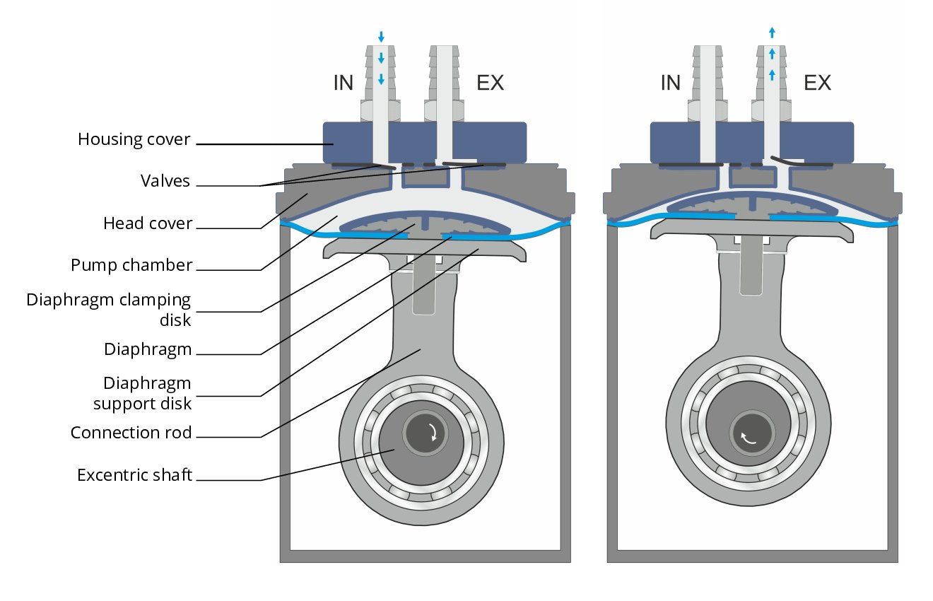
(Source: VACUUBRAND GmbH & Co. KG)
Diaphragm vacuum pumps have a single or multi-stage design. In multi-stage pumps, the pump heads are connected in series to deepen the ultimate vacuum. However, several pump heads can also be connected in parallel on one stage, which then increases the suction power.
When conveying humid gases that could condense in the pump head, care should be taken to ensure that the vacuum pump is equipped with some kind of drying system. For example, the gas ballast. In gas ballast mode, air is let into the pressure chamber through a small leakage valve. This lowers the compression ratio so that the vapour contained in the gas is expelled from the pump before it reaches its condensation point. However, the there is a minimal increase in ultimate vacuum due to this leakage compared to operation without gas ballast.
Advantages
- The diaphragm hermetically separates the delivery chamber from the pump drive. This has two advantages:
- Firstly, the pumped medium remains free of oil and lubricants and is delivered completely unadulterated.
- Secondly, the pump drive does not come into contact with the medium to be pumped. The only components that come into contact with the medium are the pump head, valves, seals and diaphragm.
- In operation, they run quietly and smoothly
Disadvantages
- Diaphragm vacuum pumps are sensitive to contamination (moisture, particles), which can severely affect their performance. If, for example, the diaphragm is damaged, this can lead to leakage and greatly reduce the suction power.
- They need regular maintenance to sustain optimal performance. This concerns the replacement of wear parts, which include the diaphragms, valves and seals.
- If aggressive gases and vapours are conveyed, care must be taken to use suitable materials (PTFE-coated diaphragm, valves/pump head made of fluorinated elastomers, etc.).
- Their field of application is in the low vacuum range up to an absolute ultimate vacuum of approx. 1 mbar. If a deeper vacuum is required, other pumps such as rotary pumps or screw pumps must be used.
Rotary pumps
These positive displacement vacuum pumps are available in many different versions designed for different applications. These four designs are among the most common:
- Dry-running rotary pumps are used for clean, dry gases.
- Oil-sealed rotary pumps use oil as a lubricant to reduce friction and wear and ensure a longer service life.
- High-vacuum rotary pumps can generate a high vacuum of up to 1x 10⁻⁶ mbar.
- Roots rotary pumps use both rotary and Roots pumps, to achieve higher efficiency and performance.
The oil-sealed rotary pumps are discussed in more detail below.
Design/function of oil-sealed rotary pumps
The pumping system of an oil-sealed rotary pump consists of a housing/stator, an eccentrically installed rotor with vanes that move radially and an intake and discharge valve. The crescent-shaped delivery chamber is divided into intake and discharge chambers. The vanes located in the rotor are pressed against the inner wall of the stator by spring or centrifugal force and divide the delivery chamber into separate chambers. When the rotor rotates, the pumped medium flows via the open intake valve into the enlarging delivery chamber (= intake chamber). During further rotation, the delivery chamber (= discharge chamber) decreases again and the enclosed delivery medium compresses. If the overpressure is high enough, the discharge valve opens and releases the medium into the atmosphere.
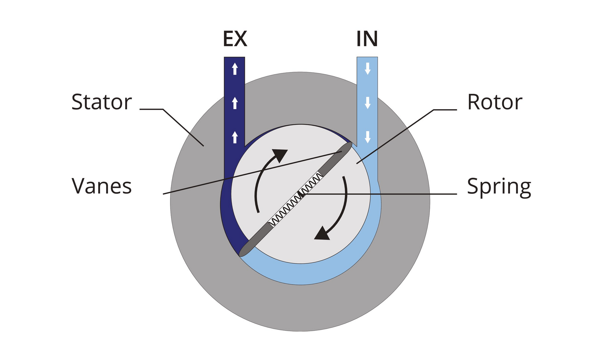
(Source: VACUUBRAND GmbH & Co. KG)
The pump oil fulfils several functions here: 1.) the efficient sealing of the delivery chamber, 2.) the lubrication of all moving parts and 3.) the heat transfer for optimum temperature equalisation. However, when using pump oil, an oil mist is released into the ambient air alongside the pumped medium, which is why an oil separator is usually installed at the outlet.
Which pump oil is suitable depends on the type of rotary pump and the application. Some manufacturers recommend special oils, while others offer a selection of standard oils. When choosing pump oil, several factors should be taken into account, such as the operating temperature of the pump, the chemical resistance of the oil to the pumped medium, and the consistency and quality of the oil.
When conveying humid gases that could condense in the pump, it should be operated in gas ballast mode. Here, air is let into the discharge chamber through a small leakage valve. This lowers the compression ratio so that the vapour contained in the gas is expelled from the pump before it reaches its condensation point. However, the there is a minimal increase in ultimate vacuum due to this leakage compared to operation without gas ballast.
Rotary vacuum pumps are available in single and two-stage versions. Two-stage pumps achieve a deeper vacuum and have a higher suction capacity at low pressures.
Advantages of oil-sealed rotary pumps
- They have a high delivery rate even at low pressures.
- Their field of application is in the medium vacuum range up to 1x 10⁻³ mbar.
- They are based on well-established technology with a very good price/performance ratio.
Disadvantages of oil-sealed rotary pumps
- They are oil-lubricated and contaminate the pumped medium with oil vapours. Furthermore, the oil becomes contaminated over time (abrasion) and can react with the pumped medium. It is therefore important to monitor the oil level and change the oil regularly to maintain the performance and service life of the pump.
- The rotation of the vanes in the pump can cause wear, which can also impact the performance of the pump over time. If the wear is too great, the wear parts must be replaced.
Screw pumps
Oil-sealed rotary pumps are increasingly being replaced by screw pumps. Screw pumps also generate a very deep ultimate vacuum, but they are dry-running, which means the medium to be pumped will not be contaminated.
Structure/functionality
Vacuum generation is based on gas transport in gap-sealed chambers: two rotating spindles intermesh without contact and, together with the stator enclosing them, form several chambers. Their very narrow clearances are in the micrometre range. While the spindles rotate synchronously in opposite directions, the chambers transport the gas. There is a mass flow along the spindle axis from the inlet on the intake side to the outlet on the discharge side. Due to the heat generated during the process, screw pumps require temperature control by means of cooling liquid or cooling air to prevent the clearances from changing. This is because the possible ultimate pressure is mainly determined by the clearances in the warm operating condition and fluid mechanical properties. The suction capacity, on the other hand, is determined, among other things, by the size of the spindles and their rotational speed.
(Source: VACUUBRAND GmbH & Co. KG)
Advantages
- Screw pumps operate 100% oil-free in the field of gas extraction and are therefore ideal for clean processes and extraction of pure products.
- They are characterised by their low maintenance requirements. The spindles intermesh without contact. This prevents abrasion and wear from occurring at all.
- They also contain no seals in the working chamber that could wear out.
- Due to the design-related high condensate compatibility, no gas ballast is required even with high steam generation.
Disadvantages
- Due to the high processing and assembly requirements, the purchase price is very high.
- Screw pumps must run hot and should only be used in the application when the ultimate pressure has been established.
Accessories for vacuum pumps
Vacuum systems
The heart of a vacuum system is the vacuum pump. A separator is fitted on the suction side to protect the vacuum pump. This retains particles and liquid droplets from the application that could enter the pump. There is also a separator on the pressure side, here called a condenser. This collects the condensate before the gas is released into the ambient air. This serves to protect the vacuum pump from condensate return and to protect the laboratory air from contamination. For low-boiling solvent vapours, an emission condenser (= high-performance condenser) can be used on the pressure side instead of the standard condenser. This allows very high solvent recovery, its cost-effective re-use and also contributes to active protection of the environment.
In simple systems, this basic equipment can be supplemented with a vacuum regulator, with which the vacuum can be adjusted manually.
In vacuum processes where an accurate, repeatable vacuum level is required, a vacuum controller is used. Controllers measure the pressure, automatically regulate the vacuum level, automatically switch the vacuum pump on and off and trigger alarms if the vacuum level is outside the desired range.
Suction systems
At its core, a liquid aspiration system consists of a vacuum pump, a collection bottle and vacuum hoses.
The vacuum pump generates a vacuum which provides the necessary suction power. It is connected on the suction side to a collection bottle, in which the extracted liquid collects. It is important to make sure that the pump does not go too deep into the vacuum so that the extracted liquid does not evaporate in the collection bottle. A blind-ended vacuum hose runs from the collection bottle, which is used to aspirate the liquid either directly or with the aid of a handle.
To protect against particles and liquid droplets, it is recommended to connect a hydrophobic PTFE filter in the hose line between the pump and the collection bottle. For increased operational safety and more convenience, quick-release couplings and a fill level detection system are helpful.
Vacuum filtration
In filtration, solids are separated from a liquid phase by passing the sample through a porous barrier. Vacuum pumps accelerate this filtration process by creating a pressure differential. Above this barrier there is atmospheric pressure (1013 mbar at sea level). Below the barrier, in the filtration bottle, the air is sucked in by the vacuum pump, creating a vacuum.
Choosing a suitable vacuum pump
The requirements for vacuum regulation and ultimate vacuum are usually modest. With filtration at 100 mbar, 90% of the atmospheric pressure is available as the driving force for filtration. Any further improvement in the vacuum level has only a minor impact on the process. In some cases, two-stage pumps, which still have a high suction capacity even at 100 mbar, may further increase the pressure differential and thus accelerate the filtration process. In these cases, vacuum limitation via a regulating valve with pressure gauge is recommended to avoid (for example) evaporation from the filtration bottle.
Selecting the right vacuum pump also depends on other factors:
- the retention range / pore size of the filter medium
- the diameter of the filter medium
- the size of the collection container
- the number of filtration units
- the type of filtering liquid (viscosity, density of suspended matter, solvents, etc.)
- the duration of the filtration
Vacuum strength
If the vacuum pump performance is too weak, the filtration process may take too long. On the other hand, if the vacuum is too strong, for example because a rotary pump is used, the following may occur:
- heavy foaming
- evaporation of the filtrate from the filter bottle
- damage/tearing of the filter medium
- a change or damage to the sample
- damage to the pump due to liquid ingress
To adapt the vacuum to the respective filtration, vacuum pumps can be equipped with a vacuum regulator incl. vacuum gauge to set the optimum conditions for filtration.
Filtration speed
The following factors influence the filtration rate:
- A high particle load can clog the filter.
- Highly viscous media are less easily drawn through the filter.
- Stronger leakages limit the achievable vacuum.
- Large filters have a greater throughput.
- Small pore sizes reduce the throughput.
Special applications
Larger collection containers or multiple filtrations require vacuum pumps with a higher delivery rate, as the space to be aspirated is larger, while viscous media or samples with a high density of suspended matter tend to need a deep ultimate vacuum.
When filtering media with a high density of suspended matter, filter slowly to begin with and then gradually increase the delivery rate to avoid the immediate formation of a dense filter cake on the fine-pored filter.

Filtration
Filtration is a physical separation process in which particles (macromolecules, micro-organisms, viruses or droplets) are separated from a fluid (gases or liquids) by means of a filter medium (e.g. paper, glass fibre or membrane filters).
► Carl ROTH offers you a comprehensive product portfolio for your filtration applications.
Filtration by means of filter papers (cellulose)
Paper filters are deep bed filters consisting of an irregular mesh of cellulose fibres obtained from (for example) wood and cotton. The proportion of α-cellulose is > 95 %. The filtration mechanism or separation effect is mainly based on mechanical retention or adsorption of particles within the filter matrix. During the filtration process, the retained particles form a secondary filter bed whose properties largely determine the further filtering process. Due to the structure and method of operation described, it is not possible to state an "absolute" pore size for filter papers; rather, it is possible only to provide information on the retention range (e.g. 4-12 µm). In addition to the retention capacity, the filtration time is also important for selecting a suitable filter paper: filtration should be quick and result in as much quantitative precipitation as possible.
Filter papers are specially optimised for their applications. In general, there are two different types of filter paper; papers for quantitative analysis and papers for qualitative analysis. They differ mainly in their ash content.
For quantitative analysis, e.g. gravimetric analysis, filter papers with a very low ash content ≤ 0.01 % are used. These special "ash-less" filter papers are characterised by the fact that they burn almost residue-free when the precipitate is annealed in a muffle furnace and thus do not affect the measurement result.
For general laboratory work, qualitative filter papers are used; the ash content here is usually ≤ 0.1 %.
Filtration by means of glass fibre filters
Glass fibre filters (borosilicate glass fibres) adsorb the finest particles up to 1 µm from liquids. Aerosols with a particle diameter < 1 µm can be separated from air and gases because the electrostatic interaction between glass fibres and gases is better than that of glass fibres and liquids. The deep structure of the glass fibre filters, with their large surface area, results in excellent particle absorption capacity with low filter resistances.
- Chemically resistant against the majority of organic and inorganic solvents, aggressive chemicals (except for hydrofluoric acid) and highly concentrated bases
- Constant weight, no significant influence on humidity fluctuations
- Mechanically stable but limited buckling strength due to the rigid fibre structure. Filter units and clamping fixtures must have flexible sealing surfaces
- Temperature stable up to 500 °C (glass fibre filter with organic binder up to 200 °C)
Filtration by means of quartz fibre filters
Quartz fibre filters made of pure quartz microfibres are suitable for airborne dust analysis and emission monitoring and also for trace analysis, due to their low content of metallic trace elements. The chemical resistance against all solvents, acids (except hydrofluoric acid) and bases is very high. The temperature resistance ranges up to 1000 °C, depending on the type of quartz fibre filter. The combination of these properties gives quartz fibre filters a special position among filters.
- High degree of purity
- High chemical resistance against organic and inorganic solvents, acids (except hydrofluoric acid) and highly concentrated bases
- Suitable for emission measurements at up to 950 °C
Filtration by means of membrane filters
Membrane filters are surface filters that have a precise micro-porous structure. During filtration, all particles larger than the pores of the membrane are retained on the surface. Smaller particles can pass through the filter but may be adsorbed on the membrane matrix by interaction with the membrane material (electrostatic and van der Waals forces). In the course of filtration, the flow rate may decrease due to clogging of the pores. This occurs especially during filtration of large volumes, samples with high particle loads or viscous media. It is therefore recommended to work under pressure or vacuum and, if necessary, to use a deep bed filter (cellulose or glass fibre) as a pre-filter. The retention capacity of the membrane filters can be as low as 0.02 µm, enabling effective retention of the smallest particles and organisms.
Not every membrane filter is suitable for every application. The following flow chart and subsequent overview of membrane materials aim to help you select the most suitable membrane material:
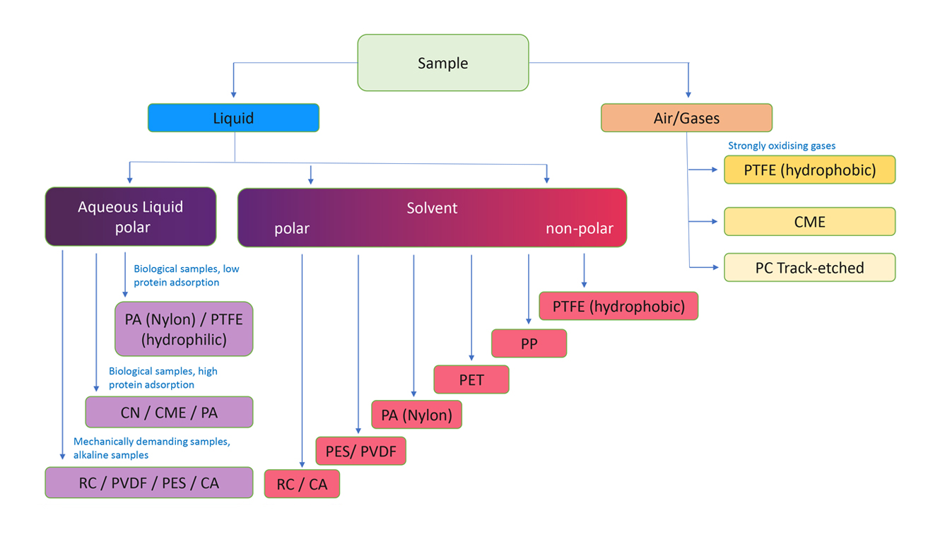
However, this chart can only be a rough approximation for your separation task; you also have to consider factors such as the chemical resistance of the different membrane materials.
Overview of membrane materials
CA (cellulose acetate)
The cellulose acetate membrane is hydrophilic. Due to their low protein adsorption, the filters with this membrane type are often used for biological samples (e.g. enzyme solutions, biological macromolecules). Other applications include clear and sterile filtration of aqueous solutions. The membrane has a high temperature stability.
CME (cellulose mixed ester)
The cellulose mixed ester membrane is a hydrophilic membrane with similar properties to CA or CN membranes as it is a mixed ester of both materials. Depending on the mixing ratio, the properties of one or the other component predominate. For example, CME filters are used for the clear filtration or sterile filtration of aqueous solutions and are sometimes also available with a printed grid to facilitate the counting of particles and micro-organisms.
CN (cellulose nitrate)
The cellulose nitrate membrane is hydrophilic and often used in microbiological investigations or generally for sample preparation of aqueous media. They contain a low proportion of extractable substances and are sometimes also available with a printed grid to facilitate the counting of particles and micro-organisms.
GF (glass fibre fleece)
The glass fibre fleece is used for pre-filtration or for filtration of samples with a high particle load. The deep structure of the filters results in a larger surface area and thus significantly greater absorption capacity for contaminant particles. The glass fibre is inert to solvents, acids and alkalis.
PA (polyamide, nylon)
The polyamide (nylon) membrane is used for filtration of HPLC and GC solvents and can also be used for the clear filtration and sterilisation of alkaline solutions. Nylon membranes are hydrophilic and resistant to many solvents and alkaline solutions. This type of membrane is characterised by high mechanical stability.
PC (polycarbonate)
Polycarbonate membranes are hydrophilic, non-hygroscopic and have a very smooth glass-like surface. Due to the track-etched manufacturing process, this membrane has a uniform and precise capillary pore structure. These membranes are used for the filtration of aqueous solutions and for gas filtration and are suitable for analyses in which the sample is viewed on the surface of the membrane. They are available in white or black.
PES (polyether sulphone)
Polyether sulphone membranes are hydrophilic and usually have low protein adsorption. They also have high flow rates compared to other membranes. This makes these filters popular products for aqueous or semi-organic media (pH range approx. 2-12), e.g. in the field of pharmaceutical and biological sample preparation.
PP (polypropylene)
Polypropylene membranes are usually mildly hydrophobic and can be used in a variety of applications due to their good chemical resistance. They can be used for both aqueous and organic media; however, the flow rates of aqueous solutions are lower than with comparable hydrophylic membranes.
PVDF (polyvinylidene fluoride)
The polyvinylidene fluoride membrane is often used for biological samples (low protein adsorption) or in pharmaceutical applications. Due to its hydrophilic properties, it is used for clear filtration and sterilisation of aqueous solutions. However, it is less suitable for the filtration of aggressive media, such as strong acids, bases and ketones.
PTFE (polytetrafluorethylene), hydrophobic
The hydrophobic polytetrafluoroethylene membrane is used for filtration of aggressive chemicals, including acids and non-aqueous solvents, as well as in GC and HPLC sample preparation. As it has a low flow resistance to gases, the membrane is also used for air and gas filtration (e.g. ventilation tasks).
PTFE membranes are very inert and usually hydrophobic (but with prior wetting with methanol or ethanol, aqueous solutions can also be filtered).
PTFE (polytetrafluorethylene), hydrophilic
Hydrophilic PTFE membranes enable the filtration of aqueous solutions without prior wetting with ethanol. For use with all common HPLC solvents. For clear filtration of acids, alkalis, cryogenic liquids and fuels. For the analysis of hydraulic fluids and for RNA isolation.
RC (regenerated cellulose)
The regenerated cellulose membrane is ideal for the filtration of biological solutions due to its low, non-specific adsorption behaviour for proteins. Another area of application is in HPLC sample preparation and in the degassing of eluents for HPLC. The membrane has a high resistance to aqueous and organic solvents.
Filtration by means of syringe adaptor filters
Syringe filters are used in combination with disposable syringes, e.g. for clear filtration or sterile filtration of small sample volumes. Syringe filters with pore sizes of 0.45 µm or 0.2 µm are usually used here. The solution is drawn up in a disposable syringe and pressed through the membrane filter of the syringe filter (pressure filtration). Typical applications are clear filtration and sterile filtration of liquids and gases as well as sample preparation for HPLC, GC, ICP, AAS, TOC, DOC, IR, NMR, photometry, spectroscopy, etc.
A major advantage compared to other filtration methods is the low dead volume that remains in the syringe filter.
Not every syringe filter is suitable for every task. The following explanatory notes are intended to assist you in selecting the appropriate syringe filter with regard to the use of different pore sizes and filter diameters.
Instructions for handling syringe filters
1. Properties of filters depending on pore size:
This table gives an overview of the cleaning options when using different pore sizes.
| Cleaning option | Pore size to be used (μm) |
| Sterile filtration | 0.2 |
| High purification | 0.45 |
| Clear filtration | 1-2 |
| Prefiltration | 5.0 |
2. Dependence of the filterable sample quantity on the filter diameter:
The following table provides an overview of the approximate sample volume that can be filtered with a filter of a certain diameter. However, depending on the particle load of the liquid to be filtered, the volume may be lower.
| Filter diameter (mm) | Sample volume (ml) |
| 3-4 | < 1 |
| 13-15 | 1-10 |
| 25 | 10-100 |
| 33 | > 100 |
3. Maximum pressure that can be generated by hand depending on syringe volume.
Depending on the size or diameter of the syringe, relatively high pressures can also be generated manually. Standard values can be found in the table below. Please observe the maximum operating pressure of each syringe filter, as exceeding it can cause the membrane to tear or the housing to burst.
| Syringe volume (ml) | Pressure (bar/psi) |
| 1 | 10 / 150 |
| 3 | 7 / 100 |
| 5 | 5 / 75 |
| 10 | 3.5 / 50 |
| 20 | 2 / 30 |
Apart from the pore size, the field of application of a syringe filter is defined mainly by the membrane material used. Not every membrane material is suitable for every application. The following flow chart and the subsequent overview of membrane materials aims to help you select the most suitable syringe filter:
This chart can only be a rough approximation for your separation task because it is important to consider the chemical resistance of the different membrane and housing materials when selecting a suitable syringe filter.
Overview of membrane materials
CA (cellulose acetate)
The cellulose acetate membrane is hydrophilic. Due to their low protein adsorption, the filters with this membrane type are often used for biological samples (e.g. enzyme solutions, biological macromolecules). Other applications include clear and sterile filtration of aqueous solutions. The membrane has a high temperature stability.
CME (cellulose mixed ester)
The cellulose mixed ester membrane is a hydrophilic membrane with similar properties to CA or CN membranes as it is a mixed ester of both materials. Depending on the mixing ratio, the properties of one or the other component predominate. For example, CME filters are used for the clear filtration or sterile filtration of aqueous solutions and are sometimes also available with a printed grid to facilitate the counting of particles and micro-organisms.
CN (cellulose nitrate)
The cellulose nitrate membrane is hydrophilic and often used in microbiological investigations or generally for sample preparation of aqueous media. They contain a low proportion of extractable substances and are sometimes also available with a printed grid to facilitate the counting of particles and micro-organisms.
GF (glass fibre fleece)
The glass fibre fleece is used for pre-filtration or for filtration of samples with a high particle load. The deep structure of the filters results in a larger surface area and thus significantly greater absorption capacity for contaminant particles. The glass fibre is inert to solvents, acids and alkalis.
PA (polyamide, nylon)
The polyamide (nylon) membrane is used for filtration of HPLC and GC solvents and can also be used for the clear filtration and sterilisation of alkaline solutions. Nylon membranes are hydrophilic and resistant to many solvents and alkaline solutions. This type of membrane is characterised by high mechanical stability.
PC (polycarbonate)
Polycarbonate membranes are hydrophilic, non-hygroscopic and have a very smooth glass-like surface. Due to the track-etched manufacturing process, this membrane has a uniform and precise capillary pore structure. These membranes are used for the filtration of aqueous solutions and for gas filtration and are suitable for analyses in which the sample is viewed on the surface of the membrane. They are available in white or black.
PES (polyether sulphone)
Polyether sulphone membranes are hydrophilic and usually have low protein adsorption. They also have high flow rates compared to other membranes. This makes these filters popular products for aqueous or semi-organic media (pH range approx. 2-12), e.g. in the field of pharmaceutical and biological sample preparation.
PP (polypropylene)
Polypropylene membranes are usually mildly hydrophobic and can be used in a variety of applications due to their good chemical resistance. They can be used for both aqueous and organic media; however, the flow rates of aqueous solutions are lower than with comparable hydrophylic membranes.
PVDF (polyvinylidene fluoride)
The polyvinylidene fluoride membrane is often used for biological samples (low protein adsorption) or in pharmaceutical applications. Due to its hydrophilic properties, it is used for clear filtration and sterilisation of aqueous solutions. However, it is less suitable for the filtration of aggressive media, such as strong acids, bases and ketones.
PTFE (polytetrafluorethylene), hydrophobic
The hydrophobic polytetrafluoroethylene membrane is used for filtration of aggressive chemicals, including acids and non-aqueous solvents, as well as in GC and HPLC sample preparation. As it has a low flow resistance to gases, the membrane is also used for air and gas filtration (e.g. ventilation tasks).
PTFE membranes are very inert and usually hydrophobic (but with prior wetting with methanol or ethanol, aqueous solutions can also be filtered).
PTFE (polytetrafluorethylene), hydrophilic
Hydrophilic PTFE membranes enable the filtration of aqueous solutions without prior wetting with ethanol. For use with all common HPLC solvents. For clear filtration of acids, alkalis, cryogenic liquids and fuels. For the analysis of hydraulic fluids and for RNA isolation.
RC (regenerated cellulose)
The regenerated cellulose membrane is ideal for the filtration of biological solutions due to its low, non-specific adsorption behaviour for proteins. Another area of application is in HPLC sample preparation and in the degassing of eluents for HPLC. The membrane has a high resistance to aqueous and organic solvents.
Filtration by means of bottle-top filters/systems (ready to use)
Bottle-top filters are sterile filtration units for direct connection to a sterile collection bottle, whereby the bottle-top filter has a vacuum connection. These systems allow uncomplicated and fast sterile filtration through the use of a vacuum source. They are available with different volume capacities, membrane materials and pore sizes.
These ready-to-use systems are mainly used for the sterile filtration of cell culture media, buffers and reagents.